
Assembling a Multicopter
Beep Beep Beep Whirr! And the mechanical bird soared up and away! Indeed, Aerial Robotics is the most intriguing field in the world of Robotics.
Summary
This blog is a guide to assemble a multicopter with an onboard low level microcontroller, starting from the very quad-root level. Hop onboard, let’s get started!
In this blog
- APM/Pixhawk - The Low Level Controller
- Motors and ESCs
- LiPo - The Power Source
- RC Transmitter and Reciever
- GPS
- Assembly
- Motor Order Diagrams
- Attaching Propellers
- Mission Planner
- Loading Firmware
- Compass Calibration
- Radio Control Calibration
- Accelerometer Calibration
- ESC Calibration
- Flight Modes
- Arming the Motors
- Fly!
- What’s next?
APM
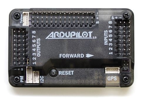
Ardupilot Mega (APM) is an IMU autopilot that is based on the Arduino Mega platform. It is capable for autonomous stabilisation, way-point based navigation and two way telemetry with Xbee wireless modules, supporting 8 RC channels with 4 serial ports. ArduPilot Mega consists of the main processor board and the IMU shield which fits above or below it.
Motors and ESCs
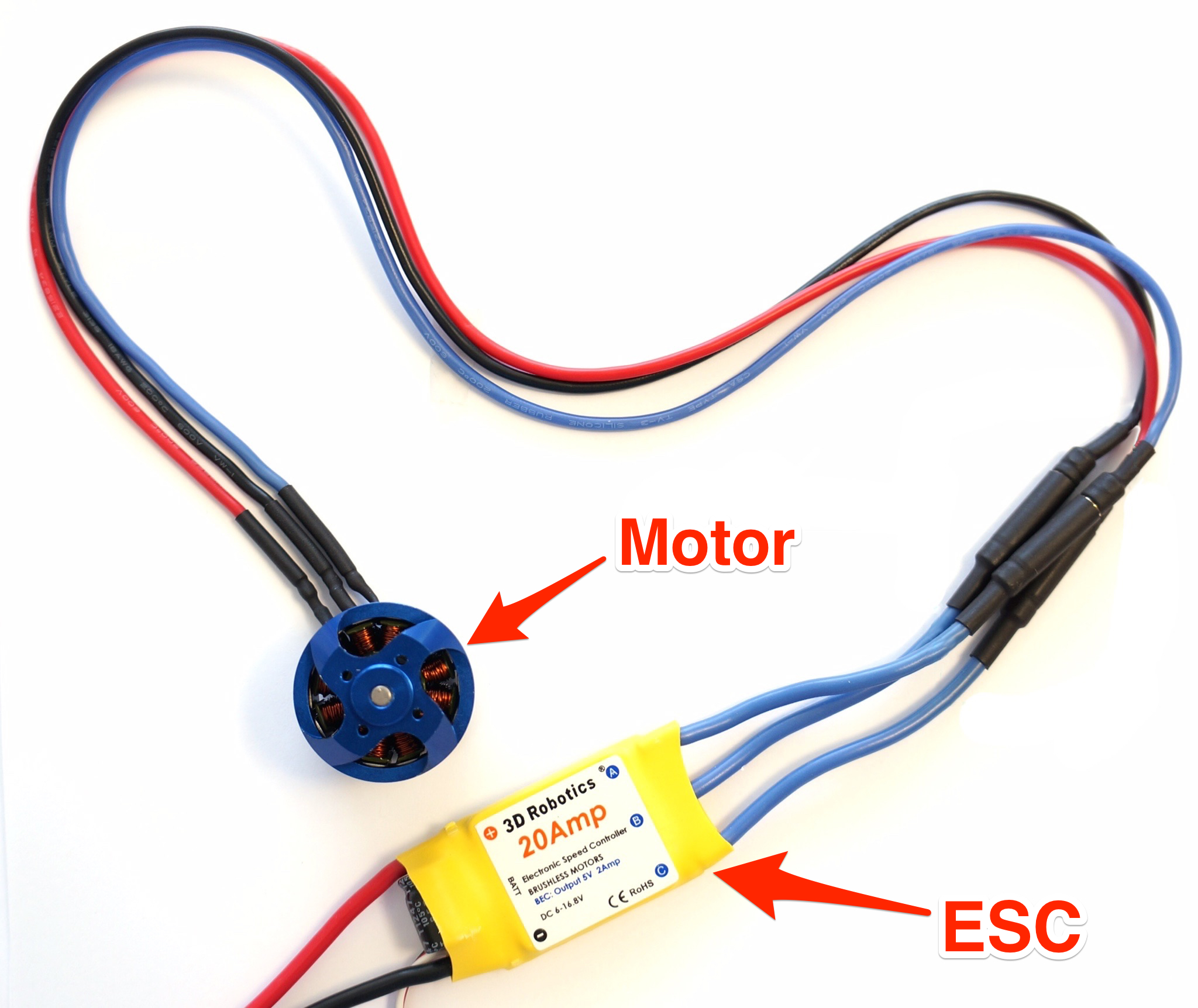
The copter uses 850kV Brushless DC Motors, each with a dedicated Electronic Speed Controller of current rating 40A. The ESCs provide electronically generated three-phase electric power low voltage source of energy for the motor. The PPM signal for the control comes from the APM. ESCs can be BEC or OPTO.
The Power Source

A Lithium Polymer battery of rating 11.1V, 3s, 5000mAh, 20C is used for powering the motors. The battery provides an average flight time of 4-6 minutes.
RC Transmitter and Reciever
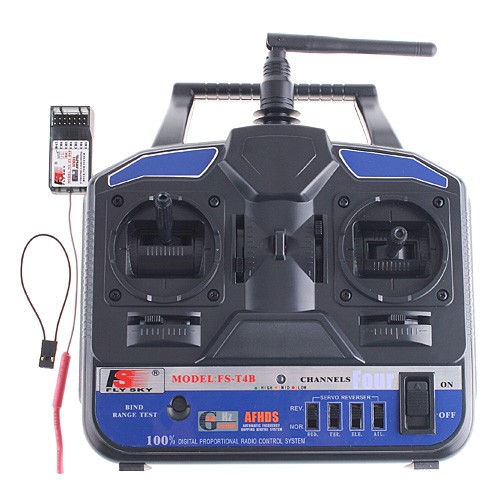
The quadcopter is controlled by a 6 channel 2.4 GHz RC transmitter and a 6 channel PPM receiver in manual mode. The bandwidth of the transmitter is 500Hz.
GPS
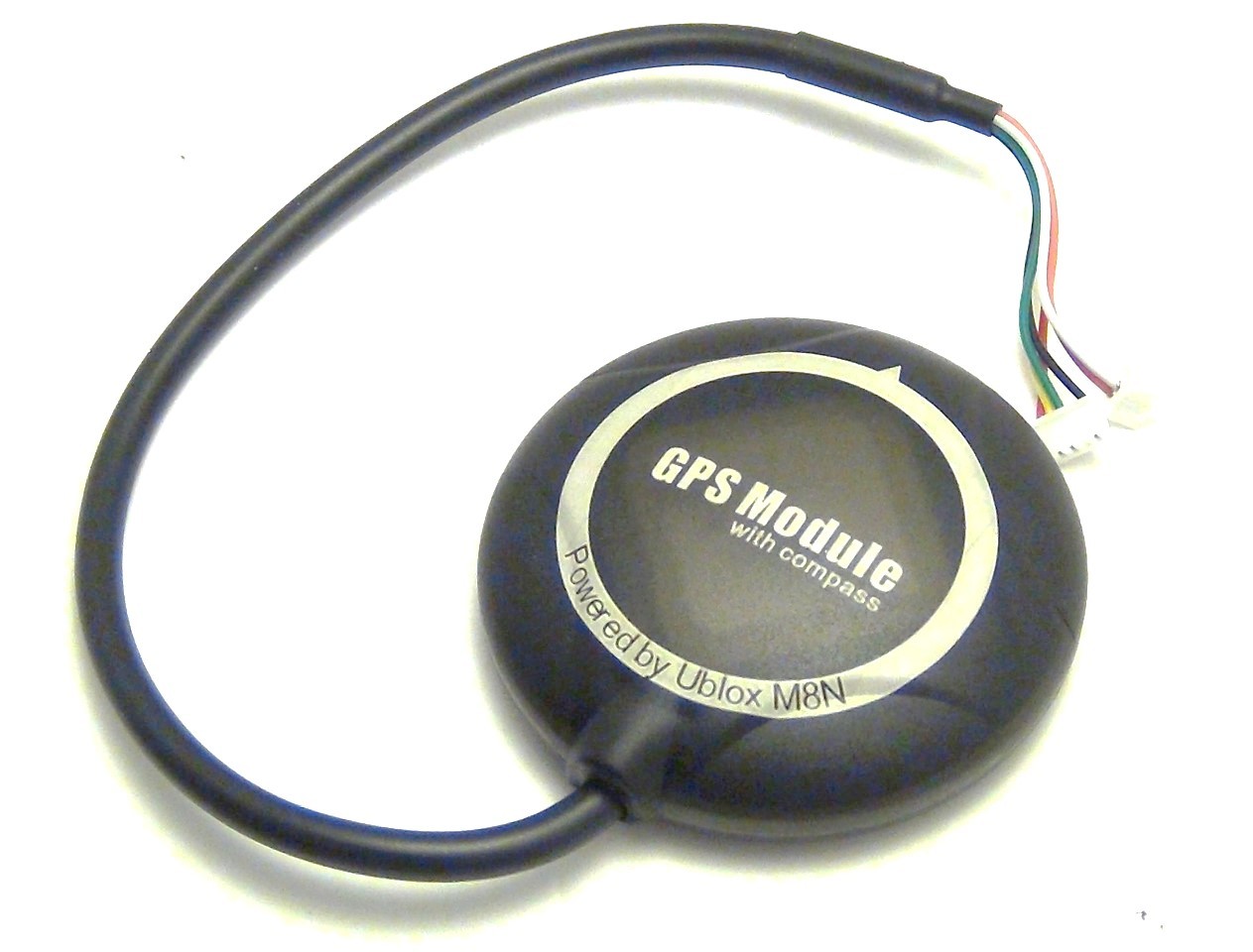
The Ublox Neo-M8N GPS module includes a HMC5883L digital compass.It outputs precise position updates at 10Hz. The Ublox NEO-M8N is configured to run at a baud rate of 38400.
Assembly
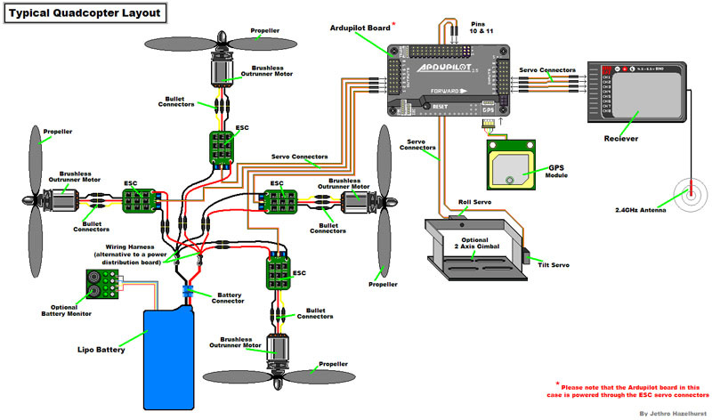
The illustration below highlights the typical installation of a quadcopter. It contains optional equipment including a Camera, Gimbal and a Battery Monitor and it utilizes an ESC wired “Y” power connection rather than the power distribution board common to many MultiCopters.
Motor Order Diagram
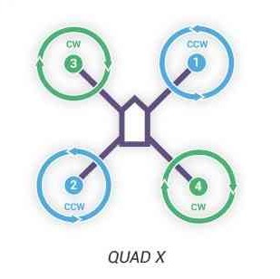
The figure shows motor order for Quad X (the numbers indicates the connected autopilot output pin) and the propeller direction (clockwise (CW) motors are shown in green and take pusher propellers,counterclockwise motors (CCW) are shown in blue and take puller propellers. Diagrams for other frames can be found on the official Arducopter Website
Attaching Propellers
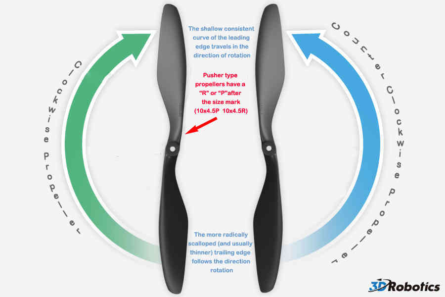
The diagrams shows two types of propellers: clockwise (called pushers) and counterclockwise (called pullers). It is most reliable to recognize the correct propeller type by its shape. Note that the propellers have the edge with the shallow consistent curve at the leading edge in direction of rotation and the more radical scalloped (and usually thinner edge) as the trailing edge.
Mission Planner
Mission Planner is free, open source software available for Windows. The latest version can be downloaded from here.
Loading Firmware
Once you’ve installed the Mission Planner onto your computer, connect the autopilot board to your computer using the micro USB cable. Windows should automatically detect and install the correct driver software.
Open the Mission Planner and select the COM port drop-down on the upper-right corner of the screen (near the Connect button). Select AUTO or the specific port for your board (PX4 FMU or Arduino Mega 2560). Set the Baud rate to 115200 as shown. Don’t hit Connect just yet.
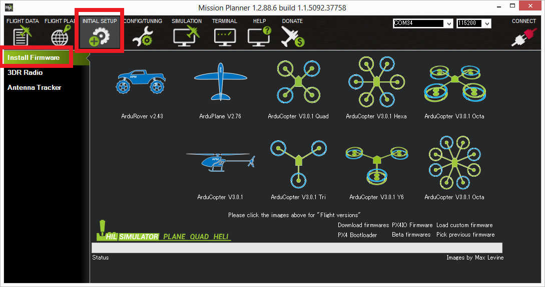
On the Mission Planner’s Initial Setup->Install Firmware screen select the appropriate icon that matches your frame (i.e. Quad, Hexa). Answer Yes when it asks you “Are you sure?”.
If all goes well you will see some status appear on the bottom right including the words, “erase…”, “program…”, “verify..” and “Upload Done”. The firmware has been succesfully uploaded to the board.

Select the desired port and data rate and then press the Connect button to connect to the autopilot. After connecting Mission Planner will download parameters from the autopilot and the button will change to Disconnect as shown.
Compass Calibration
- Under Initial Setup->Mandatory Hardware select Compass.
- Select your flight controler configuration to automatically enter the most important configuration information for your board.
- Confirm that the Enable compasses and Obtain declination automatically boxes are checked.
- Click the Live Calibration button.
- A window should pop-up showing you the state of the live calibration.
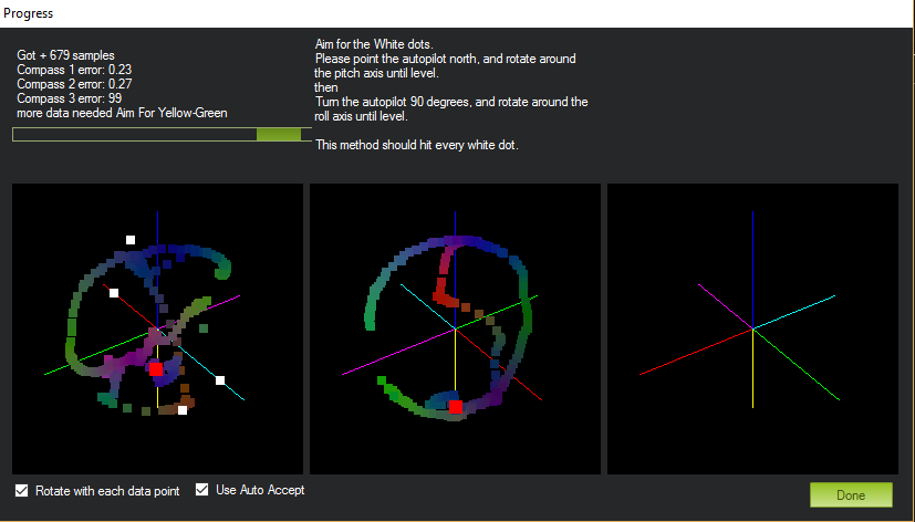
- The aim is to rotate the vehicle so that the coloured trail hits each of the white dots. One way to do this is to hold the vehicle in the air and rotate it slowly so that each side (front, back, left, right, top and bottom) points down towards the earth for a few seconds in turn.
- The calibration will automatically complete when it has data for all the positions. At this point, another window will pop up telling you that it is saving the newly calculated offsets. These are displayed on the main screen below each associated compass.
A video demonstration of the live compass calibration can be found here.
Radio Control Calibration
RC transmitters are used to control vehicle movement and orientation. Copter minimally controls throttle, pitch, roll and yaw. Each of these control signals are mapped to transmitter stick/switch(s) and in turn to autopilot channels from the connected receiver.
Copter default channel mappings are:
- Channel 1: Roll
- Channel 2: Pitch
- Channel 3: Throttle
- Channel 4: Yaw
- Channel 5: Flight modes
- Channel 6: (Optional) Inflight tuning or camera mount (mapped to transmitter tuning knob)
For safety reasons you should disconnect the battery and/or remove propellers before preforming radio calibration. Also, centre trims in manual RC mode before preforming RC calibration. If trims are not centred you may need to do the RC calibration again after you have used the vehicle.
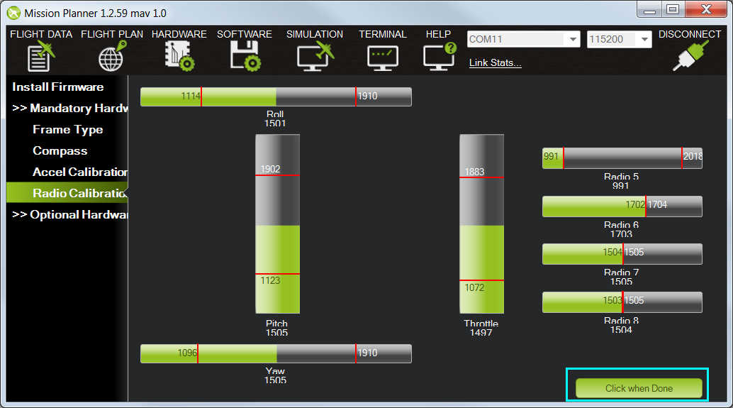
- Open Mission Planner’s INITIAL SETUP->Mandatory Hardware->Radio Calibration screen.
- Click on the green Calibrate Radio button in the lower right of the window.
- Mission Planner will display a prompt to check radio control equipment is on, battery is not connected, and propellers are not attached. Select OK.
- Move the control sticks and toggle switches on your transmitter to their limits of travel and observe the results on the radio calibration bars. Red lines will appear across the calibration bars to indicate maximum and minimum values.
- Select Click when Done when all required channels are set at the minimum and maximum positions.
Accelerometer Calibration
- Under Initial Setup->Mandatory Hardware, select Accel Calibration from the left-side menu.
- Click Calibrate Accel to start the calibration.
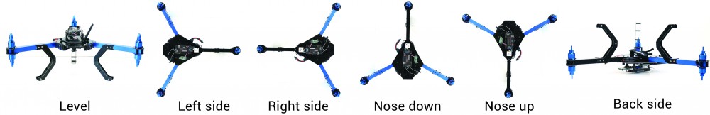
- Mission Planner will prompt you to place the vehicle each calibration position. Press any key to indicate that the autopilot is in position and then proceed to the next orientation.
The calibration positions are: level, on right side, left side, nose down, nose up and on its back.
- When you’ve completed the calibration process, Mission Planner will display “Calibration Successful!”
A video demonstration can be found here.
ESC Calibration
Electronic speed controllers are responsible for spinning the motors at the speed requested by the autopilot. Most ESCs need to be calibrated so that they know the minimum and maximum pwm values that the flight controller will send.
Before calibrating ESCs, please ensure that your copter has NO PROPS on it and that the APM is NOT CONNECTED to your computer via USB and the Lipo battery is disconnected.
- Plug one of your ESC three-wire cables into the throttle channel of the RC receiver. (This is usually channel 3.)
- Turn on the transmitter and set throttle stick to maximum (full up).
- Connect the LiPo battery. You will hear a musical tone, then two beeps.
- After the two beeps, lower the throttle stick to full down.
- You will then hear a number of beeps (one for each battery cell you’re using) and finally a single long beep indicating the end points have been set and the ESC is calibrated.
- Disconnect battery. Repeat these steps for all ESCs.
- If it appears that the ESC’s did not calibrate then the throttle channel on the transmitter might need to be reversed.
- If you are still having trouble after trying these methods (for example, ESCs still beep continuously) try lowering your throttle trim 50%.
- You can also try powering your APM board via the USB first to boot it up before plugging in the LiPo.
Once you have calibrated your ESCs, you can test them by plugging in your LiPo. Remember: no propellers!
- Ensure your transmitter’s flight mode switch is set to “Stabilize Mode”.
- Arm your copter
- Give a small amount of throttle. All motors should spin at about same speed and they should start at the same time. If the motors do not all start at the same time and spin at the same speed, the ESC’s are still not properly calibrated.
- Disarm your copter.
Flight Modes
There are a few things you need to know about the flight modes in ArduCopter before flying.
- For flying manually without GPS, fly in STABILIZE mode.
- For flying at a fixed height manually, use ALTITUDE HOLD mode.
- For flying manually with GPS use Loiter mode(it flies stably and stays at a position if you leave the controls).
You can read more about flight modes here.
Arming the Motors
-
Before proceeding, ensure that the following params are set in Config/Tuning->Full Parameter List
- THR_MIN = 130 - THR_MAX = 1000 - MOT_SPIN_ARMED = 0 - Turn on your transmitter.
- Plug in your LiPo battery. The red and blue lights should flash for a few seconds as the gyros are calibrated (do not move the copter).
- The pre-arm checks will run automatically and if any problems are found an APM2.x will double blink the red arming light, on a Pixhawk the RGB led will blink yellow.
- Arm the motors by holding the throttle down, and rudder right for 5 seconds. It takes approximately 5 seconds the first time the copter is armed as it re-initialises the gyros and barometer. Do not hold the rudder right for too long (>15 seconds) or you will begin the AutoTrim feature.
- Once armed, the red arming light should go solid.
- Raise the throttle to take-off.
Fly
Flying a multicopter is an art and it will take some time, break some propellers and explode some LiPos but you will definitely get a hold of it! Fly high, may the thrust be with you!
Here’s a video of the Hexacopter Eagle with a self-designed wooden frame:
The High Level Controller
The next step in the world of Aerial Robotics is Autonomous Flight. Odroid and Raspberry Pi are common High Level Controllers. Stay Tuned!


Aman Chandra
Software Developer. Robotics Enthusiast. Potterhead.